
Sep 24, 2026Cutting Tool Selection Guide
Carbide Drill Failure Modes: How to Read Wear Patterns and Fix Them
A practical guide to solid carbide drill failure modes: flank wear, corner chipping, margin wear and built-up edge — causes, corrective actions and buying tips
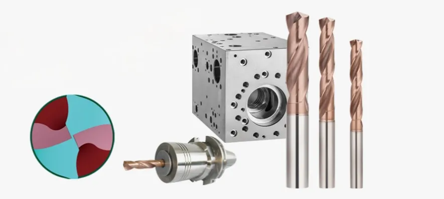
Carbide Drill Failure Modes: How to Read Wear Patterns and Fix Them
A failed carbide drill tells you exactly why it failed — if you know where to look. Almost every premature carbide drill failure falls into one of a handful of recognizable wear patterns: uniform flank wear, rapid flank wear, corner chipping, margin wear, built-up edge, or crater wear at the drill center. Each pattern points to a different root cause — cutting speed, feed, coolant, runout, or system stability — and each has a specific, practical fix.
This guide explains how to identify each failure mode, what it means for your process, and what to change before you blame the tool.
Why Carbide Drills Fail: Heat, Chips, and Stability
Drilling is different from every other cutting operation in one fundamental way: the drill is surrounded by the workpiece. The heat generated at the cutting edge has nowhere to go except into the chips, the tool, and the hole wall. When the workpiece material has low thermal conductivity — stainless steel, titanium alloys, heat-resistant superalloys — cutting temperatures at the drill point climb very quickly.
Three factors dominate drill performance and, therefore, drill life:
- Heat management. Most of the energy in drilling converts into heat. Controlling cutting temperature — and the transfer of that heat into the tool — is the core task of any drilling process.
- Stability. Drills usually run with significant overhang. The rigidity of the machine, the workpiece clamping, the toolholding system, and the drill itself all determine whether the cutting edge cuts cleanly or chips prematurely. A large share of "tool quality complaints" are actually stability problems.
- Chip evacuation. Chips must leave the hole efficiently. Chip re-cutting damages the machined surface, adds heat, and accelerates wear on both the cutting edges and the margins.
Before diagnosing any individual failure mode, check these three foundations. A failure-mode diagnosis on an unstable, poorly cooled process will lead you to the wrong conclusion.
The Main Carbide Drill Failure Modes and What They Mean
1. Uniform Flank Wear — the Pattern You Want
When flank wear develops evenly along the entire cutting edge, with the margin coating and corner radius still largely intact, the process is under control. This is the ideal, predictable wear mode: the drill degrades gradually, hole quality stays consistent, and the wear is low enough that the drill can often be reconditioned by regrinding.
As a general reference used across the tooling industry, flank wear in the range of roughly 0.1–0.3 mm is considered acceptable for many solid carbide drill applications and is usually easy to regrind. The exact limit depends on the drill diameter, the carbide grade, and the tolerance requirements of the hole.
What to do: Nothing, other than tracking wear rate. Uniform flank wear at a predictable rate is the baseline against which you judge every other failure mode.
2. Rapid Flank Wear — Heat Concentration at the Drill Point
When flank wear accelerates well beyond the normal rate, the usual cause is heat accumulation at the drill point: cutting temperature is too high. Left uncorrected, it shortens tool life, degrades hole size and surface finish, and raises your cost per hole.
Typical corrective actions:
- Reduce cutting speed. Speed is the strongest lever on cutting temperature. A 10–20% reduction often produces a disproportionate improvement in tool life, though the right value depends on the workpiece material and the carbide grade.
- Increase coolant concentration. Lubricity at the margin and the drill point matters as much as cooling capacity in many hole operations (see the coolant section below).
- Verify coolant delivery. If the drill is designed for internal coolant, confirm that holes are unblocked and pressure is adequate.
3. Corner Chipping at the Drill Point and Margin Junction
Chipping at the corner where the primary cutting edge meets the margin points to one or more of three conditions: poor process system stability, restricted chip evacuation, or excessive heat at the drill point.
Typical corrective actions:
- Reduce feed at drill entry and exit by roughly 50%. Both transitions are shock events for the cutting edge — entry because the point is not yet supported by the hole, exit because the edge breaks through the remaining material.
- Reduce cutting speed to bring cutting heat down.
- If the drill is long or heavily overhung, reduce cutting speed by around 20%. Extra overhang multiplies deflection and vibration; the process must be slowed to compensate.
- Increase coolant concentration to reduce friction and heat.
If chipping persists after these changes, the problem is likely mechanical rather than thermal — check runout (next section) and workpiece clamping before replacing the tool brand.
4. Margin Wear — Friction Against the Hole Wall
The margins (side lands) of a drill rub against the freshly machined hole wall. When margin wear becomes pronounced, friction between the margin and the workpiece surface is excessive — and that rubbing generates additional cutting heat on top of the heat from the cutting edge itself. Margin wear is strongly influenced by the workpiece material (gummy and abrasive alloys accelerate it) and by the margin and chamfer design of the drill.
Typical corrective actions:
- Reduce cutting speed.
- Increase coolant concentration to improve lubrication along the margin.
Margin wear also has a design dimension: drills with narrower margin lands and polished margins generate less rubbing heat. This is a specification question to raise with your supplier, not a parameter question.
5. Margin Wear Combined with Slight Chipping — Check Your Toolholding
When slight chipping appears alongside margin wear, the process is unstable or chip evacuation is difficult, and the margin is contacting the hole wall more than it should. Excluding drill design and manufacturing defects, the most common root cause is the toolholding system: excessive radial runout or poor clamping symmetry.
Every tenth of runout is shared unevenly between the two cutting edges, so one edge does more work than the other. The overloaded edge wears and chips first, hole size drifts, and the margin on the heavy-cut side rubs harder against the wall.
Typical corrective actions:
- Reduce radial runout — measure it at the drill point with a dial indicator, not just at the holder taper.
- Reduce cutting speed.
- Increase coolant concentration.
- Where available, specify a drill with narrower margin lands for the material in question.
Note on toolholding: any cutting tool clamping system matters in drilling, including hydraulic, shrink-fit, and precision milling chucks. Claims that "an ER collet chuck is good enough for drilling" ignore the effect of runout and asymmetry on drill life. The drilling results achievable on the same machine with the same drill can differ substantially between a low-precision collet and a low-runout system.
6. Built-Up Edge (BUE) — Cutting Temperature Is Too High or Too Low
Built-up edge is the counterintuitive failure mode: it appears both when cutting temperature is too high and when it is too low. When drilling aluminum, stainless steel, and heat-resistant alloys — materials with strong adhesion tendencies — workpiece material welds onto the cutting edge, then tears away, taking carbide particles with it. Rapid BUE formation also signals poor process system stability.
Typical corrective actions:
- If BUE forms on the margin (periphery), increase cutting speed. Slow speeds in gummy materials push the edge into the low-temperature BUE zone.
- If BUE forms at the drill point (bottom edge), increase feed. The edge needs a thicker chip to cut below the work-hardened layer.
- Increase coolant concentration. In hole operations, coolant flow, pressure, and coolant type all matter; a meaningful share of "tool quality" complaints trace back to coolant condition rather than the drill.
- Specify a grade with a more suitable coating and improved rake-face surface finish. A smoother, well-selected coating reduces the adhesion sites where BUE starts.
7. Crater (Crescent) Wear at the Drill Center
Crescent-shaped wear at the center of the drill point is primarily abrasive wear, caused by chip rubbing over the rake face combined with excessive heat accumulation at the center point — the zone where cutting speed approaches zero and the material is extruded rather than cut.
Typical corrective actions:
- Reduce feed. The center of the drill sees the highest specific pressure; excessive feed overloads it directly.
- Increase coolant concentration to reduce friction and heat.
- Select a grade with better surface finish and a coating matched to the workpiece material.
Quick Troubleshooting Table
Failure Mode | What It Looks Like | Most Likely Cause | Corrective Actions |
Uniform flank wear | Even wear land along the whole edge; margins intact | Normal, controlled process | Continue; track wear for tool-life data |
Rapid flank wear | Wear accelerates; edge dulls early | Heat at drill point; speed too high | Reduce cutting speed; increase coolant concentration; verify coolant delivery |
Corner chipping | Edge chipped at corner between cutting edge and margin | Poor stability, chip packing, or excessive heat | Cut entry/exit feed ~50%; reduce speed; reduce speed ~20% if overhang is large; raise coolant concentration |
Margin wear | Polished/worn margin lands; hole size drift | Excessive margin–wall friction | Reduce speed; increase coolant concentration; consider narrower margin design |
Margin wear + slight chipping | Worn margins plus small edge fractures | Radial runout / toolholding asymmetry | Reduce runout; reduce speed; increase coolant concentration |
Built-up edge | Workpiece material welded to edge; torn surface | Cutting temperature too high or too low; gummy materials | BUE on margin → raise speed; BUE at point → raise feed; raise coolant concentration; better coating/rake finish |
Crater wear at center | Crescent-shaped wear at drill center | Abrasive chip rubbing + heat at center | Reduce feed; raise coolant concentration; better grade/coating match |
Coolant: Pressure, Flow, and Concentration
Coolant is not an accessory in drilling — it is a process variable on the same level as speed and feed. Internal coolant is the ideal configuration for every drilling situation, and it performs three jobs at once:
- Chip evacuation. Good coolant delivery optimizes chip formation and chip transport together — the combination that determines whether drilling succeeds.
- Cooling. Since most drilling energy becomes heat, the coolant system must control cutting heat and limit its transfer into the tool.
- Margin lubrication. The margin rubs against the machined surface and generates significant heat of its own. Drills with multiple margins generate even more frictional contact, so lubrication becomes more important, not less.
Two coolant parameters do different jobs:
- Flow rate matters more for large-diameter drills, especially indexable drills. A common rule of thumb: recommended flow in liters per minute should be roughly equal to the drill diameter in millimeters.
- Pressure matters more for small solid carbide drills, where coolant must push short, broken chips out of the flute quickly — particularly critical in longer drills and deeper holes.
Concentration also depends on the material. As general starting guidelines: for steel, an emulsion concentration of roughly 6–8% is typical; for strain-hardening materials such as stainless steel, high-temperature alloys, and titanium alloys, concentration should be above 10%. These figures are process starting points — the optimum depends on the coolant brand, water quality, and the carbide grade in use.
If you must drill with external nozzle coolant, direct the jet parallel to the drill axis as closely as possible, aimed at the flutes.
Selection Criteria for Buyers: Which Drill Survives Your Process
When comparing solid carbide drills between suppliers, judge them on the factors that actually determine which failure mode you get:
Selection Factor | Why It Matters | What to Ask the Supplier |
Carbide grade | Determines the balance between wear resistance and toughness; wear resistance is not the same as hardness | Which grade for my material group? Is a tougher grade available for unstable setups? |
Coating | Controls heat and BUE formation at the edge | Which coating for stainless / titanium / aluminum? Rake face finish? |
Point geometry | Affects center load, thrust force, and chip shape | Self-centering point? Chip-splitter geometry for deep holes? |
Margin design | Determines margin friction and hole finish | Margin land width, polished margins, chamfer design |
Coolant configuration | Determines chip evacuation reliability | Coolant hole diameter and position for my hole depth? |
Diameter range and tolerance | Determines process capability | Available diameters,increments, and regrind service |
Application Scenarios Where Failure Modes Cluster
- Stainless steel and superalloys: BUE, crater wear, and rapid flank wear dominate. Coolant concentration and grade/coating selection are the deciding factors.
- Low-carbon and soft steels: BUE at low speeds and chip packing at low feeds. Slower is not always better — the goal is a reasonable speed and feed combination that keeps the edge cutting, not rubbing.
- Deep holes and long overhang: corner chipping and margin problems from instability. Expect to derate speed and prioritize coolant pressure.
- High-volume steel parts: uniform flank wear is the target; verify achievable holes-per-regrind rather than just list price.
For Distributors and Importers: What to Stock and How to Advise
If you distribute carbide drills, most end-user complaints you receive will be one of the failure modes above, not a defective drill. Being able to read a worn drill and respond with a parameter or coolant recommendation — rather than immediately swapping brands — is what turns a transactional supply relationship into a technical partnership.
From a stocking perspective:
- Cover the common failure-response scenarios with at least two options: a tougher grade for unstable machines and a wear-resistant grade for stable, high-speed operations.
- Prioritize drills with documented grade and coating specifications over generic "carbide drill" offerings, because troubleshooting advice depends on knowing what the tool actually is.
- For customers machining stainless and aerospace-type alloys, verify coolant capability (internal coolant holes, suitable coolant hole diameter) before quoting.
How CutStars Can Help
CutStars is a China-based sourcing and supply chain partner for carbide cutting tools. We do not present ourselves as the manufacturer of every product we ship; instead, we help overseas distributors, industrial suppliers, and machine shops identify and source suitable solid carbide drills, carbide inserts, and custom carbide components from specialized Chinese manufacturers — then coordinate quality, packaging, and export on your behalf.
If your current drills are failing in a specific pattern described above, send us the failed tool photos, the workpiece material, and your cutting parameters. We can help match suitable grade/coating/geometry combinations from multiple factory resources, support OEM and private-label requirements, and arrange small trial orders before you commit to volume.
FAQ
Q1: What is acceptable flank wear on a solid carbide drill? Flank wear of roughly 0.1–0.3 mm across the cutting edge is generally considered acceptable and regrindable for many applications. The practical limit depends on drill diameter, hole tolerance, and the carbide grade. Uniform flank wear within this range indicates a controlled, predictable process.
Q2: Why do my carbide drills keep chipping at the corners? Corner chipping usually indicates poor process stability, restricted chip evacuation, or excessive heat. Reduce feed at entry and exit by about 50%, reduce cutting speed, and if the drill is long or heavily overhung reduce speed by around 20%. If chipping continues, measure radial runout — toolholding asymmetry is a frequent hidden cause.
Q3: How does coolant affect carbide drill life? Coolant performs three jobs: chip evacuation, cooling, and margin lubrication. For small carbide drills, pressure matters more than flow; for large indexable drills, flow matters more (a common guideline is roughly 1 L/min per mm of drill diameter). For stainless steel and superalloys, emulsion concentration above 10% is recommended; 6–8% is a typical starting point for steels.
Q4: What causes built-up edge when drilling stainless steel? BUE forms when cutting temperature is either too high or too low for the material, and stainless steel's adhesion tendency accelerates it. If BUE appears on the margin, increase cutting speed; if it appears at the drill point, increase feed. Higher coolant concentration and a coating/rake-face finish suited to stainless also help.
Q5: Does higher carbide hardness always mean longer drill life? No. Wear resistance and hardness are not the same property. A harder grade resists abrasive wear but chips more easily under instability; a tougher grade survives unstable setups but wears faster in stable ones. The right choice depends on your machine condition, overhang, and workpiece material.
Q6: Can regrinding restore a chipped carbide drill? Uniform flank wear is straightforward to regrind. Chipped corners and BUE damage require removing more material, which shortens the drill and may alter point geometry — it depends on how much carbide remains. For repeated chipping failures, correcting the root cause is more economical than repeated regrinds.
CTA:
If you are looking for solid carbide drills, alternative drilling tooling solutions, or custom carbide components, send CutStars your application details, workpiece material, failed tool photos, or current tool model. We will help evaluate suitable sourcing options from specialized Chinese manufacturers — including OEM and private-label arrangements and small trial orders.
Internal Link Suggestions:
- Anchor Text: replaceable head drilling systems → Target Page: Replaceable Head Drilling Systems product page
- Anchor Text: carbide inserts → Target Page: Carbide Inserts product page (for readers also buying turning/milling inserts)
- Anchor Text: indexable drill insert failure → Target Page: Article 2 — "Indexable U-Drill Insert Failure: Causes and Fixes"
- Anchor Text: replaceable head drill vs solid carbide drill → Target Page: Article 3 — comparison article
- Anchor Text: custom carbide parts → Target Page: Carbide Wear Parts / Custom Carbide Components page
Next Article Opportunities:
- Indexable U-Drill Insert Failure: Causes and Fixes for Peripheral and Center Inserts — Primary Keyword: indexable drill insert failure
- Replaceable Head Drill vs Solid Carbide Drill: Which Should You Buy? — Primary Keyword: replaceable head drill
- Drilling Coolant Pressure vs Flow: How to Set Coolant for Different Drill Types — Primary Keyword: drilling coolant pressure
- How to Reduce Radial Runout in Drilling: Toolholding Best Practices — Primary Keyword: drill runout reduction
- Carbide Drill Grades and Coatings for Stainless Steel Machining — Primary Keyword: carbide drill for stainless steel